|
|
Bowlers Reference
Dual Angle Ball
Layout Technique
|
|
|

Developing an Understanding
This discussion is not intended to make you an expert ball
driller. The objective is to enhance your understanding of ball layout
considerations and more effectively communicate with your ball driller. A
second objective is to enhance your ability to make better choices as you create
an arsenal of equipment that best matches your bowling style and lane
conditions.
When a bowler purchases a high performance
ball, it is only the first step. If the ball is to perform
as expected, the pro shop measures the bowler's hand
to match the bowler's physical characteristics and capabilities. Equally
important, the technician fits the ball to the bowler's hand and accurately
tailors where the gripping holes are placed on the ball in order to match
bowler's style with the expected lane conditions. An effective ball layout
includes an accurate analysis and matching of the ball physics, the lane
conditions, the bowler's style, and the intended ball reaction. Each
bowler and ball is unique, and if the end result is to be effective, the fitting
and the ball layout is important.
It is the bowler's responsibility
to provide accurate information and data. The pro shop
technician relies on data that accurately matches the ball to
the bowler's style and objectives. The driller
interprets bowler-supplied data and the driller's
understanding to
determine an appropriate ball layout. We have covered
hand fitting techniques in other discussions, and now it is time to use this information and data. While there
are a variety of ball layout methodologies, the most
accurate method is through the use of a technique called the
Dual Angle Layout Technique.
The
Dual Angle Layout Technique is based on the physics of the
ball and the bowler's style and objectives. In this
discussion, our objective is to provide an understanding of
how layouts affect your equipment.
Since our focus is on the layout of the ball, it is first
assumed hand fitting task is known, as well as the bowler
unique Positive Axis Point (PAP) measurements. If not, you are encouraged to review
the Fitting section of this document. Also assumed is
an understanding of ball motion as it moves down the lane in
a Skid, transitions from the Skid into a turn or Hook, and
finally Rolls into the Pins.
The
Dual Angle Layout Technique breaks a layout down into three
measurements:
-
The Drilling Angle
-
The Pin to Positive Axis Point (Pin-to-PAP) distance
-
The Vertical Axis Line (VAL) angle
Each measurement has an affect on
ball motion. In addition, the relationship between
these three measurements affects ball reaction, so all three components
and their relationship to one another are important to the
final result. Let's lay out a ball, using the Dual
Angle Layout Technique,
and discuss each component separately. Afterwards, we
will discuss their interrelationship, and how they affect
ball motion as a whole. The technique begins from a
baseline which establishes the starting point for laying out
a ball.
|
|
If you were to roll an asymmetrical ball along a flat
surface, it would eventually roll with the core of the ball either
end-over-end (over the position pin) or along a lateral path (with the
position pin at the axis point). Typically, a bowling ball layout
favors the end-over-end path, and it rolls around it's Positive Axis
Point (PSA, or sometimes called the Mass Bias (MB) point.
The Ball's Preferred Roll
is over the Position Pin, and around an axis referred to as it's
Positive Spin Axis (PSA), sometimes referred to as the Mass
Bias point (MB). When creating a ball layout, these two
points (the Pin and PSA) are used as our reference points since this is
the preferred roll of the ball as it rolls toward the pins.
|
|
 |
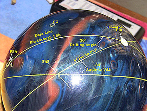
Reference Points
The ball layout is in reference to two points on a bowling ball.
Asymmetrical Ball
The ball is laid out in reference to a line drawn from the Position
Pin and the PSA since the ball core characteristics are unbalanced.
Symmetrical Ball
The ball is laid out in reference to a line drawn from the Position
Pin and the Center of Gravity (CG) in a symmetrical ball since the ball
is balanced and has no preferred spin axis. After a ball is
drilled, all balls become asymmetrical
The line drawn from the Pin and extending through the PSA or CG forms
the layout Base Line.
|
|
 |
A line drawn from the
Position Pin allows us to more precisely place the position where the
gripping holes are placed in relationship to the Position Pin. The
angle formed between the Base Line and the drawn line is referred to as
the Drilling Angle. The Drilling Angle, affects the length
of the skid phase of the ball. The higher the drilling angle,
the longer the skid phase of the ball. The smaller the drilling angle,
the quicker the transition into the hook phase of the ball. The
drilling angle limits are 10°-90°
|
|
 |
The PAP represents the Positive Axis
Point, or the initial axis of ball rotation as it is
released. The PAP is the reference point for ball
layouts. The Pin to PAP distance (Pin Length) dictates how much flare
potential the ball will have as
it travels down the lane. The more the ball flares, the more
fresh parts of the surface contacts the lane, and the more the
ball ultimately hooks. Flare Potential, is determined by the
Total Differential of an undrilled ball. Ball
manufacturers measure and publish the ball's total
differential (Diff). The higher the total differential, the higher the flare potential.
The lower the total differential, the lower the flare
potential. The maximum allowed total differential is
0.060" as set by the USBC. The Pin to PAP distance
determines how much of that flare potential is used.
The Pin to PAP distance can range from 0"
to 6.75". The maximum flare is achieved with a Pin to
PAP distance
of 3 3/8″. Think of the circumference of the
ball as approximately 27". Half way around the ball is
27"/2 or 13.5" (180°). One quarter around the ball, or
90°, is equal to 13.5" / 2 = 6.75". 1/8th the
circumference, or 45°, is 6.75" / 2 = 3.375 or 3 3/8".
This is the most unstable position of the ball, or the area
having the maximum flare potential.
A measured distance from the Pin defines the Positive
Axis Point (PAP) location.
The Pin to PAP distance
affects the percentage of the flare potential available; the length
and total hook.
The Locator Pin to PAP
distance limits are 0"-6.75".
Stable location - The Pin is located on the PAP (0"
Pin-to-PAP).
As you increase towards 2 3/4", flare increases, so
the ball typically hooks more overall.
Shorter distances
results in more boards covered in the hook such as heavier volumes of
oil.
Between 2 3/4" and 3
3/8", the ball retains axis rotation longer and thus comes off the break
point harder. The maximum track flare is equal to maximum
traction. Higher flare decreases total length and
increases the total hook of the ball.
Between 3 3/8" and 5",
the ball comes off the break point slower, but still strong.
Medium distances should be used for medium volumes of oil, but still
hook. Lower flare increases total length and lessens the total
hook of the ball.
At greater than 5",
the ball loses axis rotation quickly and thus is very flat off the spot.
Largest distances should be used to play straightest, because the ball
will not recover on inside to outside angles. |
|
 |
The Angle to
the Vertical Axis Line (VAL)
The Vertical Axis Line (VAL) is a line
that passes through the bowler's Positive Axis Point (PAP)
and Negative Axis Point (NAP) when extended completely
around the ball. The VAL separates the top and bottom
of the ball on the bowler's initial axis of rotation.
It is parallel to the bowler's grip centerline, and
perpendicular to the midline. The VAL is used to
establish the placement of the gripping holes.
The Vertical Axis Line (VAL) is
established by drawing a line through the PAP at a
predetermined angle (the VAL Angle). The VAL angle
should be no less than 20° nor more than 70°, and determines how quickly the ball
will transition from hook to roll; how long the
ball remains in the hook phase.
Minimum 20° angle causes the
ball to rev up quickly, and transitions fastest from the breakpoint into
the roll.
Maximum 70° angle
results in the ball to rev up slowest, and transition slowest from the
breakpoint into the roll.
Smaller Angles to the VAL lowers the Radius of
Gyration (RG), and increases the total differential of the ball. This
results in the ball revving up faster and transitioning faster from the
hook into the roll phase of the ball.
Larger Angles to the VAL raises the RG, and decreases
the total differential of the ball. This results in the ball revving up
slower and transitioning slower from the hook into the roll phase of the
ball.
|
|
 |
- The Drilling Angle affects the length of the skid
phase of the ball. The higher the drilling
angle, the longer the skid phase of the ball. The
lower the drilling angle, the quicker the transition
into the hook phase of the ball. The drilling
angle limits are 10°-90°.
- The Angle to the VAL affects how quickly the ball
transitions through the hook phase of the ball; how long
the ball remains in the hook phase. The Angle
to VAL limits are 20°-70°. Smaller angles rev up
faster and transition faster from hook into the roll
phase of the ball.
- The Locator Pin to PAP distance affects the
percentage of the ball's flare potential available;
the length and total hook. Lower flare
increases total length and lessens the total hook of the
ball. The Locator Pin to PAP distance limits are
0"-6.75".
|
|
 |
Locating the
Gripping Holes The Midpoint of the Gripping holes are located in
relationship to the VAL and PAP. All accurate drilling techniques
measure from the PAP back to the Midpoint of the grip using the vertical
and horizontal components of the bowler's axis coordinates determined
during the bowler's fitting.
The Grip Center Line is parallel with the VAL. It is placed by
drawing a Mid-Line which is perpendicular to the VAL.
A point is placed along the VAL using the bowler's
vertical axis component and measured from the PAP.
The Mid-Line is drawn from that point and
perpendicular from the VAL. Using the bowler's horizontal axis
coordinates, the Mid-Line extends from the VAL to the bowlers Center
Line. This point is the mid point between the thumb hole to the bottom
edge of the finger holes.
The gripping holes are located along the Center
Line as determined during the bowler's fitting.
|
|
 |
How
quickly the ball transitions from skid to hook to roll can be shaped
using the sum of the drilling angle and angle to the VAL. The sum of
the angles determines how quickly the ball transitions from skid to
hook to roll. The smaller sum of the angles changes more quickly.
The shape of the breakpoint is established by the
ratio of the drilling angle to the angle to the VAL. The larger the
ratio, the later the transition, and the sharper the breakpoint … more
back end.
The smaller the ratio, the sooner the ball transitions
into a roll.
If the sum of the two angles is small, the ball will
transition quickly. If the sum of the two angles is large, the ball will
transition slowly. The sum of the angles should be restricted between
30° and 160° to be effective.
The drilling angle should be 10° - 90°, and the angle
to the VAL should be 20° - 70°
|
Small Angle Sums (30-80) should
be used for:
Long oil patterns (>42')
Higher volumes of oil on the lane
Speed dominant bowlers
High axis tilt bowlers |
High Angle Sums (110-160) should
be used for:
Shorter oil patterns (< 35')
Lower volumes of oil on the lane
Rev dominant bowlers
Low axis tilt bowlers |
|
Medium Angle Sums (80-110) should be used when revs and speed
match, and medium oil patterns (36'-40') |
|
|
|
Measurement is the first step that leads to control
and eventually to improvement.
If you can't measure something, you can't
understand it.
If you can't understand it, you can't control it.
If you can't control it, you can't improve it." |
|

Thanks for visting
|
 Bowler
 Ball & Pins
 Home
Home Lanes
Lanes Information